2,691,340 تومان
در حال حاضر موجود نمی باشد
موجودی در حال ارسال به انبار
-
5 عدد1404/07/04
علاقه مندان : 6 نفر
وضعیت : فعال
تعداد مرجوعی : 1
دنبال کنندگان : 7 نفر
قدمت : 10 سال و 1 ماه و 11 روز
وزن : 162 گرم
کل فروش : 81 عدد
تعداد سفارش ها : 80 سفارش
4 از 5.0 با 13 رای
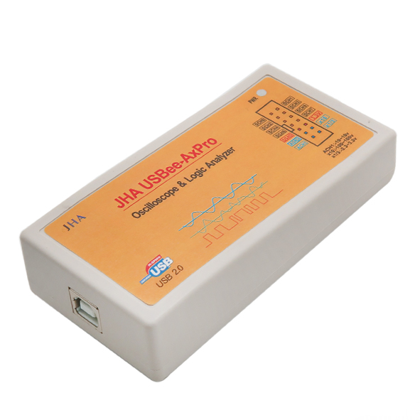
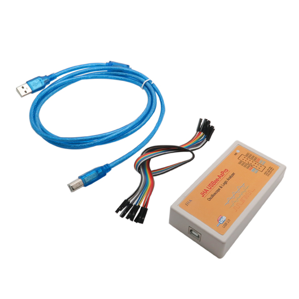
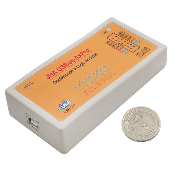
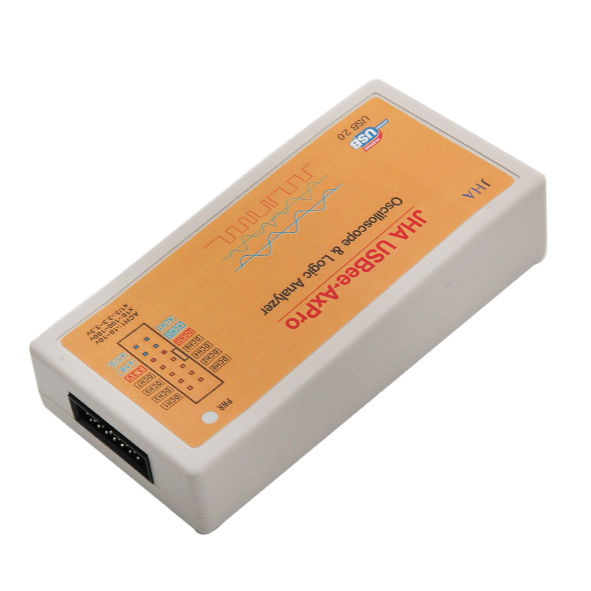
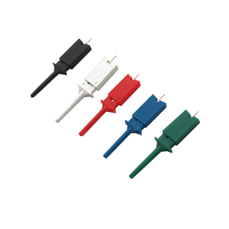
ست کامل اسیلوسکوپ و لاجیک انالایزر هشت کاناله JHA USBEE-AXPRO
توجه: لطفاً پیش از خرید، بخش مستندات و مشخصات فنی کالا را به دقت مطالعه فرمایید.
لاجیک آنالایزر ابزاری الکترونیکی است که چندین سیگنال را از یک سیستم دیجیتال یا مدار دیجیتال رکورد کرده و نمایش می دهد. یک آنالیزور منطقی ممکن است داده های گرفته شده را به timing diagrams، رمزگشایی پروتکل، state machine traces، زبان assembly یا تبدیل assembly با نرم افزار سورس Level تبدیل کند. لاجیک آنالایزر از قابلیت های تریگر پیشرفته ای برخوردار است و وقتی کاربر نیاز به بررسی timing relationships بین بسیاری از سیگنال ها در یک سیستم دیجیتال داشته باشد، بسیار مفید است. بسیاری از نمونه های دیجیتالی، از جمله مدل های IC برای تشخیص نقص قبل از ساخت unit شبیه سازی می شوند. این شبیه سازی معمولاً logic analysis displays را ارائه می دهد. اغلب، complex discrete logic با شبیه سازی ورودی ها و آزمایش خروجی ها و با استفاده از boundary-scan تأیید می شود. لاجیک آنالایزر می تواند نقایص سخت افزاری را که در شبیه سازی یافت نمی شوند ، پیدا کند. مدل سازی در این شبیه سازی ها بسیار مشکل و زمان بر است.
این ست کامل اسیلوسکوپ و لاجیک آنالایزر هشت کاناله JHA USBEE-AXPRO دارای دو نشانگر است که علاوه بر نشانگر پاور می تواند رنگ را مطابق با وضعیت اتصال تغییر دهد. بخش ورودی پاور 500 میلی آمپر را می توان توسط فیوز محافظت شده ریکاور کرد. کلیه ورودی های آنالوگ و دیجیتال با دیود Schottky و تجهیزات محافظت کامل رایانه ها محافظت می شوند. ورودی آنالوگ ازcompensation capacitor برخوردار است. شکل موج اندازه گیری به خصوص اندازه گیری سیگنال های با فرکانس بالا دقیق بوده و پهنای باند آنالوگ به 5 مگاهرتز می رسد. این دستگاه از ورودی اسیلوسکوپ (تک کانال ، 16 مگابایت ، پهنای باند 3 مگاهرتز) و آنالیزور منطقی 8-CH برخوردار است. با نرم افزار مناسب می توان از آن به عنوان رکوردر داده، ولت متر، اسیلوسکوپ سیگنال میکس، تحلیلگر منطق، فرکانس سنج، کنترل از راه دور، کنترلر PWM، ژنراتور فرکانس، کنترلر I2C و شمارنده Pulse / Edge استفاده کرد.
قبل از اتصال این دستگاه به رایانه این محصول باید درایورهای USBee AX (Standard ، Plus و Pro) را دانلود کنید.
به عنوان اسیلوسکوپ real-time، این ست کامل اسیلوسکوپ USBee AX بهترین انتخاب است.
کاربرد مجموعه کامل اسیلوسکوپ و لاجیک آنالایزر 8 کاناله :
- عیب یابی و تعمیر تجهیزات الکترونیکی
- آزمایشگاه و پروژه های علمی
مشخصات مجموعه کامل اسیلوسکوپ و لاجیک آنالایزر 8 کاناله :
- تعداد کانال ورودی: 2 عدد
- تعداد کانال نمونه برداری: یک عدد
- ماکزیمم فرکانس نمونه برداری: 16 مگاهرتز
- حداکثر پهنای باند آنالوگ: 3 مگاهرتز
- ولتاژ ورودی: - 10 تا 10 ولت
- حساسیت: 78 میلی ولت
- حداکثر رزولوشن: 256
- تعداد کانال دیجیتال: 8 عدد
- ولتاژ ورودی دیجیتال: -1 تا 6 ولت
- آمپدانس ورودی: 100k
- مجهز به محافظت تخلیه الکترواستاتیکی ESD ورودی
- پشتیبانی از SPI, IIC, UART, SMBus, I2S, CAN, Parallel, Custom, Search, Async, 1-Wite, PS / 2
- تعداد پین: 14 عدد
Description:
A logic analyzer is an electronic instrument that captures and displays multiple signals from a digital system or digital circuit. A logic analyzer may convert the captured data into timing diagrams, protocol decodes, state machine traces, assembly language, or may correlate assembly with source-level software. Logic analyzers have advanced triggering capabilities, and are useful when a user needs to see the timing relationships between many signals in a digital system. Logic analyzers are useful for identifying timing problems and compile larger numbers of digital signals.
Logic analyzers are widely used to develop and debug electronic logic circuits, they display traces of multiple logic channels and reveal the circuit operation.
Many digital designs, including those of ICs, are simulated to detect defects before the unit is constructed. The simulation usually provides logic analysis displays. Often, complex discrete logic is verified by simulating inputs and testing outputs using a boundary-scan. Logic analyzers can uncover hardware defects that are not found in simulation. These problems are typically too difficult to model in simulation, or too time-consuming to simulate and often cross multiple clock domains.
Oscilloscopes display the change of an electrical signal over time, with voltage and time as the Y- and X-axes, respectively, on a calibrated scale.
features:
1. The simulation has three input terminals: x1 (ACH1), x10, x1 / 3, which can meet general measurement (+/- 10v, x1 input), and high voltage measurement (+/- 100v, x10 input, software display) The value x10 is the actual voltage), and it can also meet the low-voltage high-precision measurement (range +/- 3.3V, resolution 25mV, x1 / 3 input, the software display value x1 / 3 is the actual voltage).
2. Two-color indicator, besides the power indicator, the color can be changed according to the connection status.3. Power input portion 500mA recoverable added protection fuse, all analog, and digital inputs are protected with a Schottky diode, full protection equipment, and computers.4. The analog input has a compensation capacitor, and the measurement waveform is accurate, especially the measurement of high-frequency signals is more accurate, and the analog bandwidth reaches 5Mhz. It features Oscilloscope Input (single channel, 16Msps, 3MHz bandwidth) and 8-CH Logic Analyzer. With suitable software it can be used as Data Recorder, Voltmeter, Mixed Signal Oscilloscope and Logic Analyzer, Frequency Meter, Remote Controller, PWM Controller, Frequency Generator, I2C Controller and Pulse / Edge Counter.
The product does not come with any software or documentation. To get it working you need to go to download and get there USBee AX (Standard, Plus, and Pro) software+drivers before connecting the device to a computer.
For a real-time oscilloscope view, the USBee AX Oscilloscope is the best choice. It provides a traditional real-time oscilloscope view to signals. There were also signal generation tools, and they all worked well…
Analog part parameters:
Number of input channels: 2 channels
Sampling channels: 1 channel
One way to achieve dual-channel tracking: frequency electronic switch
Maximum sampling frequency: 16MHz
Maximum analog Bandwidth: 3MHz
Input voltage range: -10V ~ 10V
Can withstand limit input: -20V ~ 20V
Sensitivity: 78mV
Maximum resolution: 256
The digital part parameters:
Number of channels: 8
Input voltage: -1V ~ 6V
Input Low:
Input High: >1.6V
Input impedance: 100K
Input Protection: ESD protection input clamp protection
The resolution supports the proposal: SPI, IIC, UART, SMBus, I2S, CAN, Parallel, Custom, Search, Async, 1-Wite, PS / 2
Pin Number: 14 Pins
