688,140 تومان
کالا موجود استموجودی انبار : 199 عدد
علاقه مندان : 11 نفر
وضعیت : فعال
تعداد مرجوعی : 0
دنبال کنندگان : 17 نفر
قدمت : 9 سال و 1 ماه و 16 روز
وزن : 191 گرم
کل فروش : 4446 عدد
تعداد سفارش ها : 641 سفارش
3 از 5.0 با 13 رای
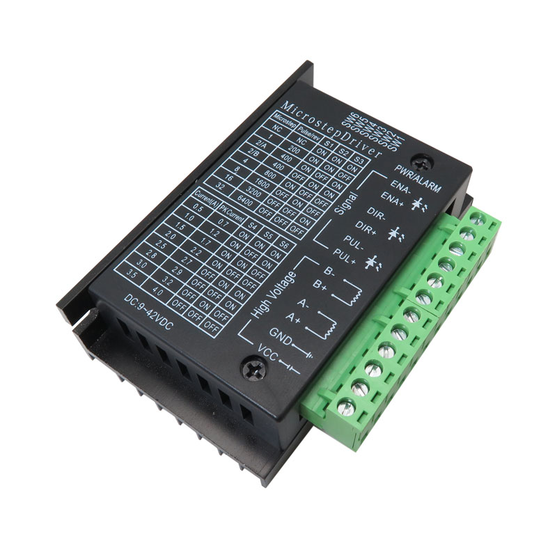
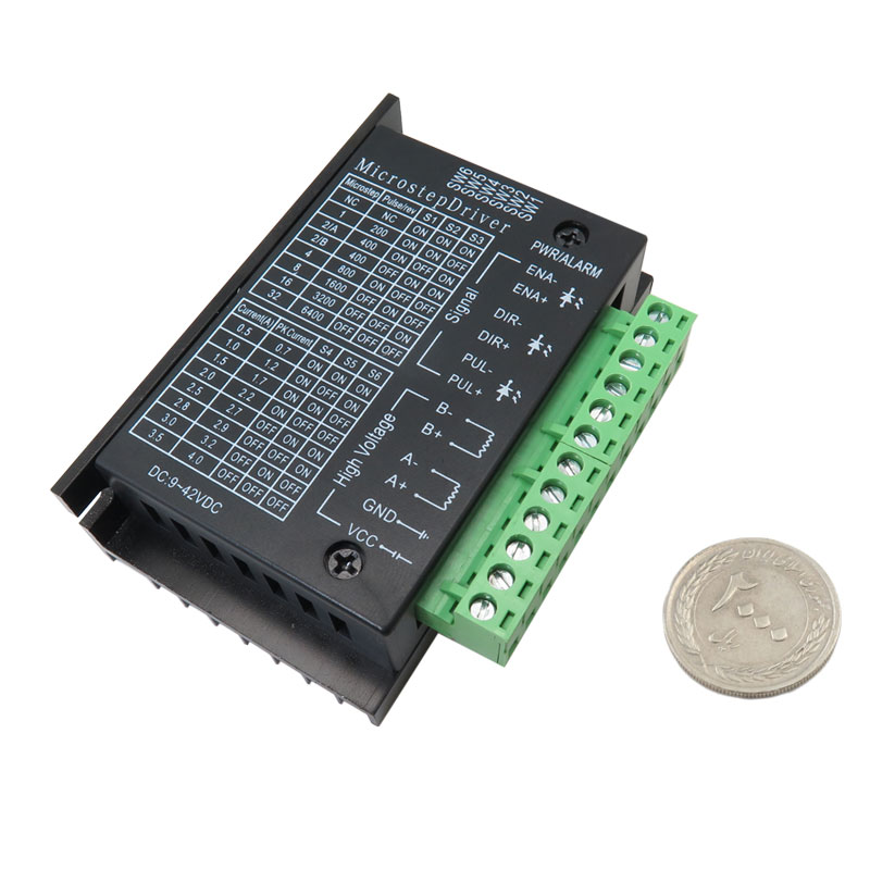
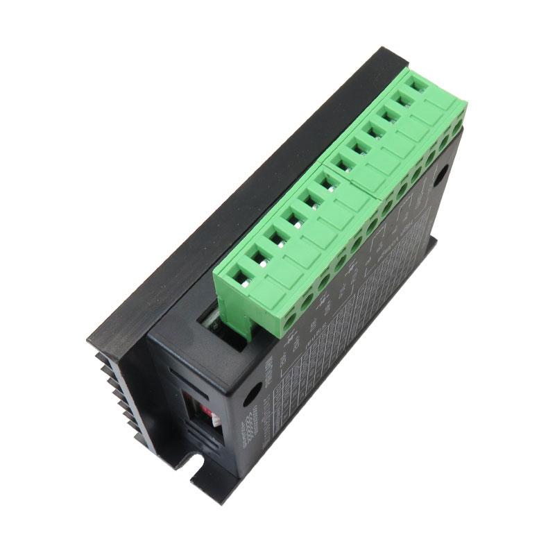
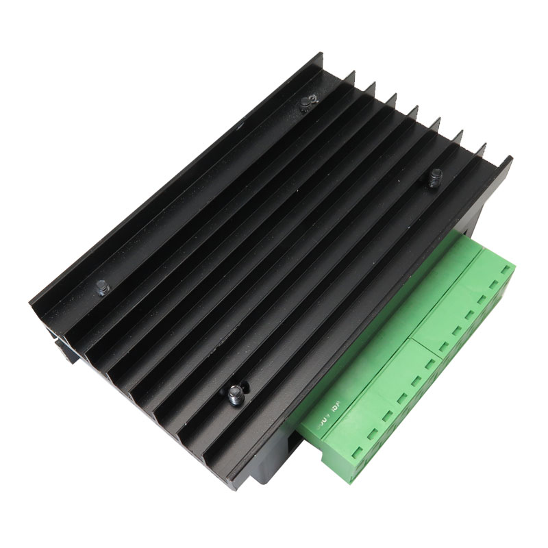
درایور استپر موتور TB6600 با بدنه پلاستیکی 4 آمپر
درایور استپر موتور TB6600 یک گزینه حرفه ای و قدرتمند برای کنترل انواع استپ موتورهای دو فاز و چهار فاز محسوب می شود که در پروژه های صنعتی ، رباتیک و سیستم های موقعیت گیری با دقت بالا مورد استفاده قرار می گیرد. این درایور مبتنی بر آی سی های ساخت شرکت توشیبا طراحی شده و در مدل های بدنه پلاستیکی از چیپ اقتصادی TB67S109 استفاده شده که با وجود کاهش قیمت ، همچنان از نظر عملکرد کاملا قابل اتکا است.
یکی از ویژگی های مهم این درایور استپر موتور 4 آمپر توان خروجی بالا در کنار کنترل PWM و تکنولوژی Chopper موجب شده تا این مدل درایور ، انتخابی عالی برای پروژه هایی باشد که نیاز به دقت در حرکت و تنظیم زاویه گام دارند. به لطف طراحی هوشمند و مدار داخلی ایزوله شده با اپتوکوپلر ، این درایور مصرف جریان بهینه ای دارد و از آسیب در برابر نویز و اختلال های الکترومغناطیسی نیز جلوگیری می کند.
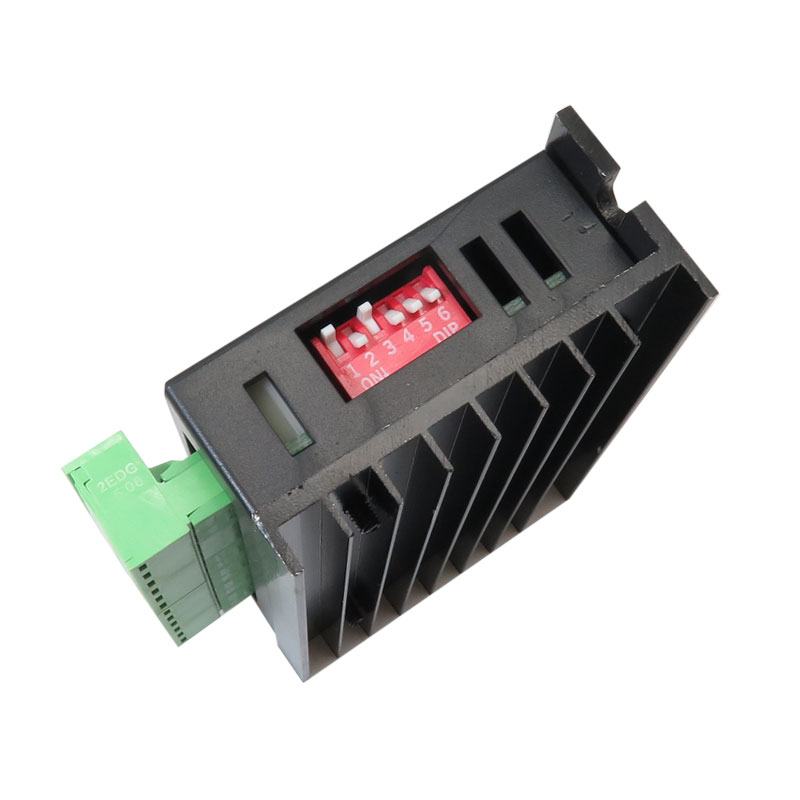
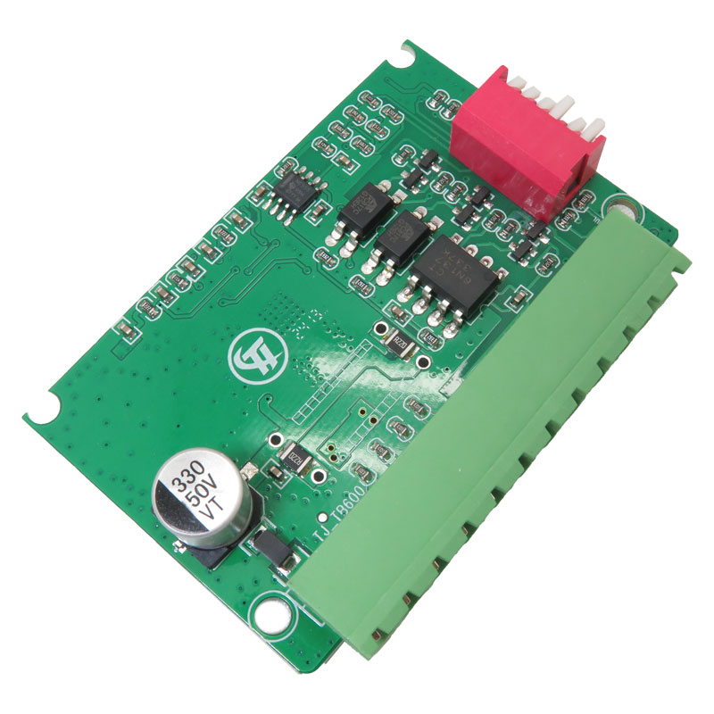
این درایور از منبع تغذیه ای در بازه 9 تا 42 ولت DC پشتیبانی می کند و می تواند تا 4 آمپر جریان اوج را تامین کند. سازگاری کامل با بردهای آردوینو و میکروکنترلرهای تولیدکننده پالس دیجیتال 5 ولت ، استفاده از آن را در پروژه های DIY و صنعتی بسیار ساده کرده است. استپر موتور TB6600 همچنین دارای 6 عدد دیپ سوئیچ است که امکان تنظیم 7 حالت مختلف میکرو استپ را فراهم می کند و همچنین جریان خروجی را می توان در 8 سطح مختلف تنظیم نمود.
درایور TB6600 به مدارهای محافظ داخلی در برابر دمای بیش از حد ، اتصال کوتاه ، جریان بیش از حد و همچنین اتصال معکوس مجهز شده است. این امکانات موجب شده تا در پروژه هایی که پایداری سیستم اهمیت دارد ، TB6600 یک انتخاب مطمئن و ایمن باشد. از جمله کاربردهای رایج این درایور میتوان به دستگاه های CNC ، ماشین های حکاکی ، لیبل زن ها ، سیستم های برش لیزری و پرینتر های سه بعدی اشاره کرد.
اگر به دنبال بهترین درایور استپ موتور 4 آمپر برای CNC هستید ، درایور TB6600 با عملکرد پایدار ، قابلیت تنظیم دقیق و قیمت مناسب ، میتواند نیازهای شما را به بهترین شکل برآورده کند. این محصول برای کسانی که به دنبال دقت ، دوام و کیفیت بالا هستند ، گزینه ای بی رقیب در بازار محسوب میشود.
ورودی سیگنال :
+CP : ترمینال ورودی مثبت سیگنال پالس-CP : ترمینال ورودی منفی سیگنال پالس
+DIR : ترمینال مثبت کنترل جهت چرخش موتور
-DIR : ترمینال منفی کنترل جهت چرخش موتور
+EN : ترمینال مثبت برای فعال یا غیرفعال کردن موتور
-EN : ترمینال منفی برای فعال یا غیرفعال کردن موتور
اتصال سیم پیچ موتور :
+A : اتصال به فاز مثبت سیمپیچ A-A : اتصال به فاز منفی سیمپیچ A
+B : اتصال به فاز مثبت سیمپیچ B
-B : اتصال به فاز منفی سیمپیچ B
اتصال ولتاژ کاری :
VCC : ورودی مثبت تغذیه DC (توجه : ولتاژ بین 10 تا 42 ولت DC)GND : ورودی منفی تغذیه DC
نحوه اتصال اپتوکوپلر ورودی سیگنال :
دو روش برای اتصال سیگنال های ورودی وجود دارد : اتصال آند مشترک یا اتصال کاتد مشترک . انتخاب نوع اتصال بستگی به نوع طراحی سیستم کنترل شما دارد .- اتصال آند مشترک : در این روش ، پایههای CP+ ، DIR+ و EN+ مستقیماً به خروجی تغذیه سیستم کنترل متصل میشوند . اگر منبع تغذیه 5 ولت باشد ، اتصال مستقیم ممکن است ، اما اگر ولتاژ بیشتر از 5 ولت باشد ، باید یک مقاومت محدودکننده جریان (R) در مسیر قرار گیرد تا جریان بین 8 تا 15 میلیآمپر برای تحریک اپتوکوپلر تأمین شود . سیگنال پالس از طریق CP- اعمال میشود . در این حالت پایههای DIR- و EN- دارای سطح پایین منطقی (Low) مؤثر هستند .
- اتصال کاتد مشترک : در این روش پایههای CP- ، DIR- و EN- به زمین سیستم کنترل (SGND که باید از زمین منبع تغذیه ایزوله باشد) متصل میشوند . سیگنال پالس 5 ولت از طریق پایه CP+ تزریق میشود . در این حالت پایههای DIR+ و EN+ سطح بالا (High) مؤثر دارند . مقدار مقاومت محدودکننده جریان مشابه روش آند مشترک در نظر گرفته میشود .
نکته مهم :
زمانی که پایه EN فعال نیست (یعنی درایور در حالت آزاد قرار دارد) ، شفت موتور قابل چرخش دستی خواهد بود . این ویژگی برای تنظیم دستی موقعیت روتور بسیار مفید است . پس از اتمام تنظیم دستی ، میتوانید پایه EN را دوباره فعال کنید تا کنترل اتوماتیک موتور از سر گرفته شود .
کاربرد :
- استفاده در دستگاه برش لیزری صنعتی برای کنترل دقیق موقعیت محورهای حرکتی
- راه اندازی دستگاه سی ان سی رومیزی جهت حکاکی و برش چوب ، پلکسی یا فلزات نرم
- کنترل استپر موتور در ماشین لیبل زن جهت جابهجایی دقیق رولهای بستهبندی
- به کارگیری در پرینتر سه بعدی برای کنترل دقیق محورهای حرکتی و میز چاپ
مشخصات فنی درایور استپر موتور TB6600 :
- ولتاژ تغذیه DC مستقیم : 9 تا 42 ولت
- حداکثر جریان خروجی : 4 آمپر (قابل تنظیم در 8 سطح مختلف)
- حداکثر جریان پیک چیپ اصلی : تا 5 آمپر در 100 میلی ثانیه
- تعداد حالت میکرو استپ : 7 حالت (1 ، 2 / A ، 2 / B ، 4 ، 8 ، 16 ، 32)
- نوع کنترل جریان : پل H از نوع جریان ثابت دو قطبی
- ایزولاسیون سیگنال ورودی : اپتوکوپلر با سرعت بالا
- رابط سیگنال پالس : پالس تک با پلاریته مثبت
- حفاظت داخلی : محافظت در برابر دمای بالا ، اتصال کوتاه ، جریان بیش از حد و اتصال معکوس
- قابلیت عملکرد آفلاین : امکان چرخش دستی شفت موتور در حالت آزاد
- بدنه : نیمه محصور مناسب محیطهای سخت
- قابلیت قفل جریان نیمه خودکار برای صرفه جویی در انرژی
- پشتیبانی از استپر موتورهای دو فاز و چهار فاز با سیم بندی 4 ، 6 و 8 سیم
- سطح ولتاژ سیگنال کنترل : 3.3 تا 24 ولت (سازگار با آردوینو و میکروکنترلرهای 5 ولتی)
- فرکانس ورودی پالس : تا حدود 20 کیلوهرتز
- نسخه چیپ در بدنه پلاستیکی : TB67S109
- نسخه چیپ اصلی صنعتی : TB6600HG
- مقاومت داخلی : حدود 0.4 اهم
- دمای کاری : منفی 10 تا 45 درجه سانتی گراد
- ابعاد : حدود 96 × 56 × 33 میلی متر
- وزن : تقریبا 200 گرم
ویژگی ها:
- منابع تغذیه 9 ولت و 24 ولت
- راه اندازی پل دو قطبی H
- جریان خروجی قابل تنظیم با حداکثر جریان 8 آمپر
- دارای عملکرد قفل جریان نیمه خودکار برای کاهش مصرف انرژی
- ایزوله کردن سیگنال ورودی نوری با سرعت بالا
- رابط تک پالس مثبت استاندارد
- عملکرد نگهداری آفلاین
- دارای شاسی نیمه محور با قابلیت انطباق با شرایط محیطی سخت
- دارای عملکرد محافظت از دما و جریان زیاد
مستندات:
دانلود راهنمای راه اندازی درایور استپر موتور TB6600 با آردوینو
Description:
TB6600 Arduino Stepper Motor Driver is an easy to use professional stepper motor driver, which could control a two-phase stepping motor. It is compatible with Arduino and other microcontrollers that can output a 5V digital pulse signal.TB6600 Arduino stepper motor driver has a wide range of power input, 9~42VDC power supply. And it is able to output 4A peak current, which is enough for most of the stepper motors.
This driver is an upgraded version of TB6600, heightening segments to 32 segments, for high-use segments.
Features:
42,57,86type 2-phase 4-phase (4-wire line 6 line 8)1. 9V-42V DC power supply
2. H - bridge bipolar constant - current driving
3. The maximum 4.0A eight selectable output current
4. Maximum 32 segments six Subdivision optional
5. The input signal high-speed optical isolation
6. The standard total positive single pulse interface
7. Offline maintenance function
8. Semi-enclosed chassis can be adapted to a more stringent environment
9. To provide energy-saving semi-automatic current lock function
10. Built-in temperature protection and overcurrent protection
Terminal definitions:
Signal input:1. The CP +: positive pulse signal input terminal.
2. CP-: pulse signal input negative terminal.
3. The DIR +: the motor is, reverse control of the positive terminal.
4. The DIR -: the motor is, reverse control negative terminal.
5. EN +: motor off control of the positive terminal.
6. EN-: motor off control of the negative terminal.
Motor Winding Connection:
1. A +: Connect the motor windings A + phase.
2. A-: Connect the motor windings A- phase.
3. B+: Connect the motor winding B + phase.
4. B-: Connect the motor winding B- phase.
Operating Voltage Connection:
1. The VCC: Positive DC power supply (Note: 10V < the VCC < 42V).2. The GND: DC power supply negative.
Signal input optocoupler isolation connection
There are two input signal interface connections: the user may need to use a common anode or common cathode connection.
1. Common anode connection: respectively, the CP +, the DIR +, EN + is connected to the power supply control system, if the power supply is + 5V can be connected directly if the power supply is greater than + 5V, should be an additional external current limiting resistor R and lt, guaranteed to drive internal optical coupling provides 8-15mA drive current.
Pulse input signal CP- access; In this case, the DIR -, EN- in low effective.
2. Common cathode connection: respectively CP-, the DIR -, EN- connected to the control system ground terminal (SGND, isolated from power ground); + 5V pulse input signal by CP + added; In this case, the DIR +, EN + in high effective.
Limiting resistor R is connected in the same values and common anode connection.
NOTE:
"EN end" does not take EN valid when the rotor is in a free state (offline), then the motor shaft can be rotated manually, do for your adjustment. After manual adjustment is completed, then EN is set to an invalid state to continue the automatic control.
