224,880 تومان
کالا موجود استموجودی انبار : 181 عدد
علاقه مندان : 10 نفر
وضعیت : فعال
تعداد مرجوعی : 12
دنبال کنندگان : 14 نفر
قدمت : 7 سال و 4 ماه و 7 روز
وزن : 48 گرم
کل فروش : 931 عدد
تعداد سفارش ها : 209 سفارش
1 از 5.0 با 1 رای
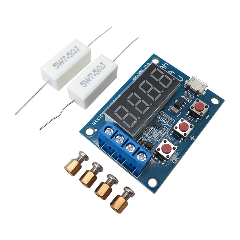
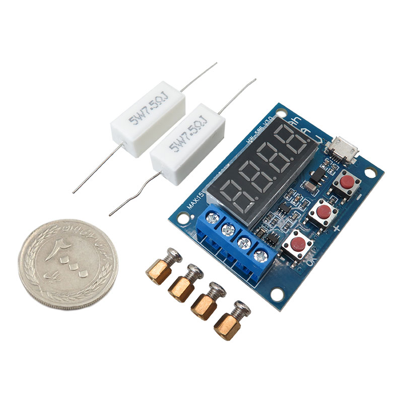
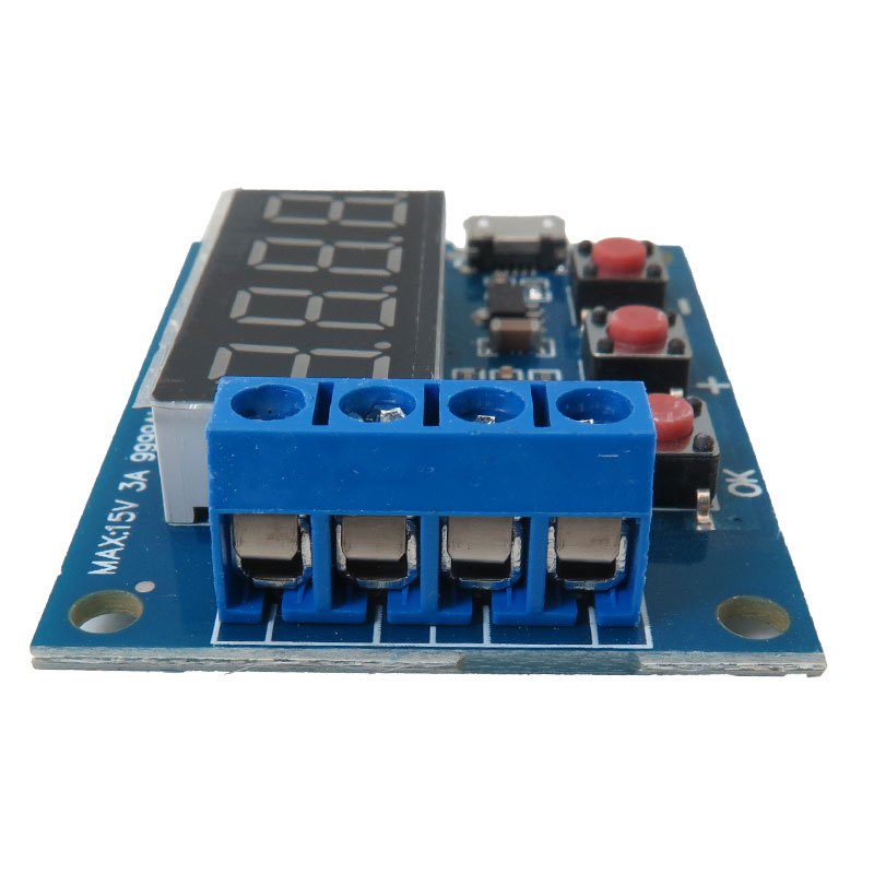
ماژول تست ظرفیت دشارژ باتری
مقاومت موجود در پکیج تنها جهت تست موقت ماژول است. جهت تست بلند مدت نیاز به مصرف کننده مطمئن خواهید داشت.
ماژول تستر ظرفیت باتری لیتیوم یون ZB2L3 برای اندازهگیری عملکرد باتریها طراحی شده است. برای استفاده از این تستر، باتری باید کاملاً شارژ شده و بهدرستی به ورودیهای مشخص شده متصل شود. این تستر از طریق USB تغذیه میشود.
نحوه استفاده از ماژول ZB2L3:
1.ابتدا باتری مورد آزمایش باید کاملاً شارژ شود.
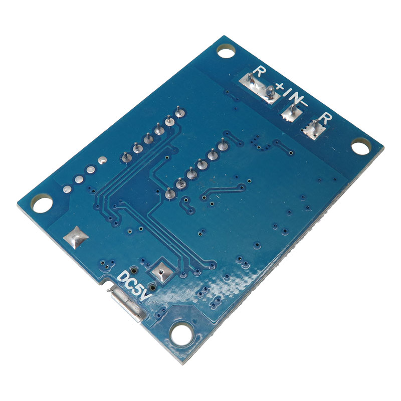
2.قطب مثبت باتری را به ورودی مثبت و قطب منفی آن را به ورودی منفی متصل کنید. توجه داشته باشید که اتصال معکوس ممکن است به مدار آسیب برساند. بار را به خروجی مثبت و منفی متصل کنید. برای تأمین قدرت، تستر را از طریق میکرو USB به منبع تغذیه وصل کنید . در این مرحله، ولتاژ باتری نمایش داده خواهد شد.
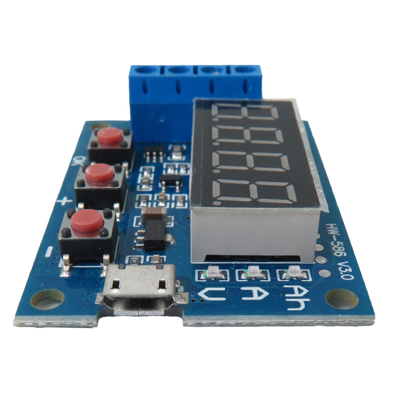
3.برای آغاز آزمایش، دکمه "OK" را فشار دهید. تستر بهطور خودکار ولتاژ پایان مناسب را با توجه به ولتاژ شارژ کامل باتری تنظیم میکند و صفحه نمایش را سه بار چشمک میزند. اگر نیاز به تنظیم دستی ولتاژ پایان باشد، میتوانید با فشار دادن دکمههای "+" یا "-" وضعیت نمایش ولتاژ باتری را تغییر دهید. ولتاژ پایان به عنوان مقدار شروع چشمکزن "E" نمایش داده میشود و وضوح 0.1 ولت دارد. پس از تنظیم، دکمه "OK" را فشار دهید تا آزمایش آغاز شود.
4.پس از شروع آزمایش، تستر سوئیچ الکترونیکی را که بار را کنترل میکند فعال میسازد. دادههای فرآیند آزمایش به ترتیب زیر نمایش داده میشوند: ولتاژ فعلی (V)، جریان تخلیه (A)، ظرفیت آزاد شده (Ah)، زمان تخلیه (Min) و ولتاژ پایان (E). با فشار دادن دکمههای "+" و "-" میتوانید مقادیر را بهصورت دستی تغییر دهید. هنگامی که ولتاژ باتری به ولتاژ پایان تنظیم شده رسید، تستر بار را قطع کرده و ظرفیت (Ah) را نمایش میدهد که بهسرعت با نشانگر "Ah" چشمک میزند. برای نمایش پایدار دادهها، دکمه "OK" را فشار دهید. پس از آن، میتوانید با فشار دادن دکمههای "+" و "-" ولتاژ پایان، ولتاژ متوسط، جریان متوسط، ظرفیت و زمان تخلیه را بررسی کنید. دوباره دکمه "OK" را فشار دهید تا به حالت آمادهبهکار بازگردید و تست باتری جدیدی آغاز کنید.
کد خطا و معانی آن:
Err1: ولتاژ باتری بالاتر از 15 ولت است.
Err2: ولتاژ باتری کمتر از ولتاژ پایان تنظیم شده است.
Err3: باتری نمیتواند جریان تخلیه بار را تحمل کند یا مقاومت داخلی بالا است.
Err4: جریان خیلی زیاد است (بیش از 3.1A).
Err5: استفاده نادرست یا خطای سیمکشی باعث سوختن دستگاه شده و قابل استفاده نیست (ممکن است نمونهبرداری یا سوئیچ کنترل MOS سوخته باشد).
عملیات کالیبراسیون ثانویه:
برای ورود به حالت کالیبراسیون، سه دکمه را همزمان فشار داده و نگه دارید تا تستر روشن شود. ابتدا تعداد رکوردهای کالیبراسیون را نمایش میدهد و سپس به برنامه نمونه کالیبراسیون رسمی نمایشگر 0u0A وارد میشود. ورودی مثبت و منفی را اتصال کوتاه کنید و سپس دکمه "OK" را فشار دهید تا نمایشگر J10u تکمیل شود. ولتاژ DC استاندارد 10.00 ولت را بین قطبهای مثبت و منفی ورودی اعمال کنید و دوباره دکمه "OK" را فشار دهید. سپس J2.0A نمایش داده میشود؛ جریان DC ثابت 2.0A را به قطب منفی خروجی و مثبت ورودی اعمال کنید و دکمه "OK" را برای تکمیل کالیبراسیون فشار دهید. تستر دادههای کالیبراسیون را بررسی میکند. اگر دادهها قابل اعتماد باشند، عدد 4 را نمایش میدهد و سپس خارج میشود؛ در غیر این صورت، دادهها کنار گذاشته میشوند.
توجه:
به منظور بهبود دقت اندازهگیری ولتاژ، این مدار بهطور ویژهای طراحی شده است تا افست DC را جبران کند. در صورتی که ترمینال متصل نباشد، ولتاژ کمی نمایش داده میشود که تأثیری بر اندازهگیری واقعی ندارد. اگر ترمینال ورودی را اتصال کوتاه کنید (0 ولت مطلق)، نمایشگر عدد 0 را نشان خواهد داد. برای درک بهتر این اصل، میتوانید به مطالعه قضیه برهمنهی در مهندسی برق بپردازید.
هنگام استفاده از تخلیه مقاومت، بار مقاومت به شدت گرم میشود؛ بنابراین، لطفاً به ایمنی توجه کنید! از مقاومت پوسته آلومینیومی 50 وات استفاده کنید و آن را بر روی صفحه فلزی نصب نمایید تا از ایمنی و کارایی بهتر اطمینان حاصل شود.
کاربرد ماژول تست ظرفیت دشارژ باتری:
- اندازهگیری ظرفیت باتری
- تحلیل عملکرد باتری
- کالیبراسیون باتریها
- پروژههای الکترونیکی
مشخصات تست ظرفیت باتری لیتیومی:
- ولتاژ منبع تغذیه: DC4.5-6V (کانکتور میکرو USB)
- جریان عملیاتی: کمتر از 70 میلی آمپر
- ولتاژ تخلیه: 1.00-15.00 ولت، وضوح 0.01 ولت
- محدوده ولتاژ پایان: 0.5-11.0V
- جریان پشتیبانی شده: حداکثر 3.000A، وضوح 0.001A
- حداکثر خطای اندازه گیری ولتاژ: 1% + 0.02 ولت
- حداکثر خطای اندازه گیری جریان: 0.008 ± 1.5% A
- حداکثر محدوده ظرفیت باتری: 9999Ah (1Ah = 1000mAh) مقدار بیشتر با جابجایی نقطه اعشار تغییر می کند، زمانی که کمتر از 10Ah باشد X.XXX نمایش داده می شود، تا 10Ah یا بیشتر XX.XX و غیره نمایش داده می شود.
اقلام ماژول ZB2L3:
- 1 عدد تستر ظرفیت باتری
- 1 x 7.5 اهم مقاومت 5W
Description:
The ZB2L3 Lithium-ion Battery Capacity Tester Module is designed to measure the performance of batteries. To use this tester, the battery must be fully charged and properly connected to the specified inputs. This tester is powered by USB.
How to use the ZB2L3 module:
1. First, the battery under test must be fully charged.
2. Connect the positive pole of the battery to the positive input and the negative pole to the negative input. Note that reverse connection may damage the circuit. Connect the load to the positive and negative outputs. To supply power, connect the tester to the power supply via micro USB. At this point, the battery voltage will be displayed.
3. Press the "OK" button to start the test. The tester will automatically adjust the appropriate end voltage according to the battery's full charge voltage and flash the screen three times. If you need to manually adjust the end voltage, you can switch the battery voltage display mode by pressing the "+" or "-" buttons. The end voltage is displayed as the flashing start value "E" and has a resolution of 0.1V. After setting, press the "OK" button to start the test.
4. After starting the test, the tester activates the electronic switch that controls the load. The test process data is displayed in the following order: current voltage (V), discharge current (A), released capacity (Ah), discharge time (Min) and end voltage (E). You can manually change the values by pressing the "+" and "-" buttons. When the battery voltage reaches the set end voltage, the tester will disconnect the load and display the capacity (Ah) which will flash rapidly with the "Ah" indicator. Press the "OK" button to display the data stably. After that, you can check the end voltage, average voltage, average current, capacity and discharge time by pressing the "+" and "-" buttons. Press the "OK" button again to return to standby mode and start a new battery test.
Error code and its meaning:
Err1: Battery voltage is higher than 15V.
Err2: Battery voltage is lower than the set end voltage.
Err3: Battery cannot withstand the discharge current or internal resistance is high.
Err4: Current is too high (more than 3.1A).
Err5: Improper use or wiring error has caused the device to burn out and cannot be used (the sampling or MOS control switch may be burned out).
Secondary calibration operation:
To enter the calibration mode, press and hold the three buttons at the same time until the tester turns on. First, it displays the number of calibration records, and then enters the official calibration sample program of the display 0u0A. Short-circuit the positive and negative input, and then press the "OK" button to complete the display J10u. Apply a standard DC voltage of 10.00V between the positive and negative terminals of the input and press the "OK" button again. Then J2.0A is displayed; apply a constant DC current of 2.0A to the negative terminal of the output and the positive terminal of the input and press the "OK" button to complete the calibration. The tester checks the calibration data. If the data is reliable, it will display 4 and then exit; otherwise, the data will be discarded.
Note:
In order to improve the accuracy of voltage measurement, this circuit is specially designed to compensate for DC offset. If the terminal is not connected, a small voltage will be displayed, which has no effect on the actual measurement. If you short-circuit the input terminal (absolute 0V), the display will show 0. To better understand this principle, you can study the superposition theorem in electrical engineering.
When using resistor drain, the resistor load will be very hot; therefore, please pay attention to safety! Use 50W aluminum shell resistor and install it on a metal plate to ensure better safety and performance.
Application:
Battery Capacity Measurement
Battery Performance Analysis
Battery Calibration
Electronics Projects
Specifications:
Power supply voltage: DC4.5-6V (Micro USB connector)
Operating current: Less than 70mA
Discharge voltage: 1.00-15.00V, resolution 0.01V
End voltage range: 0.5-11.0V
Supported current: Max. 3.000A, resolution 0.001A
Maximum voltage measurement error: 1% + 0.02V
Maximum current measurement error: 0.008 ± 1.5% A
Maximum battery capacity range: 9999Ah (1Ah = 1000mAh) The larger value changes by moving the decimal point, when less than 10Ah, X.XXX is displayed, up to 10Ah or more, XX.XX is displayed, etc.
