22,680 تومان
کالا موجود استموجودی انبار : 19 عدد
علاقه مندان : -
وضعیت : فعال
تعداد مرجوعی : 0
دنبال کنندگان : -
قدمت : 6 سال و 1 ماه و 9 روز
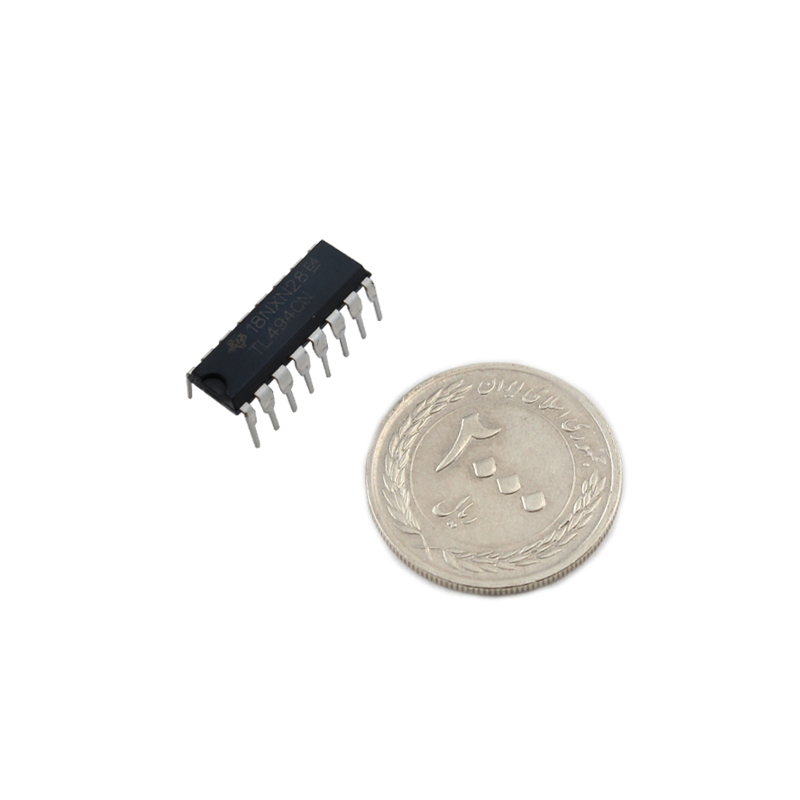
وزن : 1 گرم
کل فروش : 781 عدد
تعداد سفارش ها : 130 سفارش
هنوز هیچ رایی ثبت نشده است
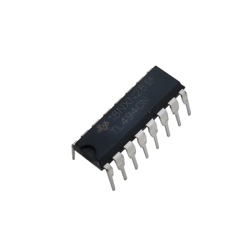
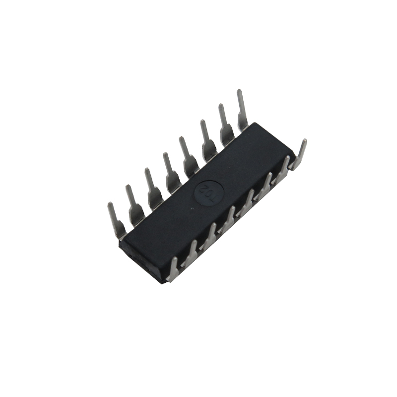
آی سی TL494CN دارای پکیج DIP16
**این کالا قابل مرجوع شدن نمیباشد.**
آی سی TL494 یک کنترل کننده مدولاسیون عرض پالس (PWM) با فرکانس ثابت می باشد که تمام المان های مورد نیاز برای تولید یک موج PWM را دارد. با استفاده از این آی سی به راحتی می توانید یک موج PWM با مشخصات مورد نظرتان را بسازید و برای اهداف مختلف استفاده کنید. این آی سی دارای پکیج dip16 است و از دو مدار مقایسه کننده، رگولاتور، اسیلاتور قابل تنظیم تشکیل شده است. TL494CN به دلیل انعطاف پذیری بالا، عملکرد پایدار و قیمت مناسب، یکی از محبوبترین آی سی ها در حوزه الکترونیک قدرت است. این آی سی به طور گسترده در منابع تغذیه سوئیچینگ، اینورترها و سایر کاربردهای کنترل توان استفاده می شود.
کاربرد آی سی TL494CN دارای پکیج DIP16:
- کنترل سرعت موتورها
- منابع تغذیه سوئیچینگ
- مانیتورهای رومیزی
- مایکرویو
- اینورترهای کوچک خورشیدی
- آشکارسازهای دود
مشخصات آی سی TL494CN:
- ولتاژ خروجی: 40 ولت(حداکثر)
- جریان خروجی: 200 میلی آمپر (حداکثر)
- فرکانس سوئیچینگ: 300 کیلوهرتز
- duty cyle: %45
- زمان رایز: 100 نانو ثانیه
- زمان فال: 40 نانو ثانیه
- محدوده دمای کاری: 70 ~ 0 درجه سانتی گراد
مستندات:
دیتاشیت TL494CN
Description:
The TL494 device incorporates all the functions required in the construction of the pulse-width modulation (PWM) control circuit on a single chip. Designed primarily for power-supply control, this device offers the flexibility to tailor the power-supply control circuitry to a specific application.
The TL494 device contains two error amplifiers, an on-chip adjustable oscillator, a dead-time control (DTC) comparator, a pulse-steering control flip-flop, a 5-V, 5%-precision regulator, and output-control circuits.
The error amplifiers exhibit a common-mode voltage range from –0.3 V to VCC – 2 V. The dead-time control comparator has a fixed offset that provides approximately 5% dead time. The on-chip oscillator can be bypassed by terminating RT to the reference output and providing a sawtooth input to CT, or it can drive the common circuits in synchronous multiple-rail power supplies.
Applications:
Desktop PCs
Microwave Ovens
Power Supplies: AC/DC, Isolated, With PFC, > 90 W
Server PSUs
Solar Micro-Inverters
Washing Machines: Low-End and High-End • E-Bikes
Power Supplies: AC/DC, Isolated, No PFC,
Power: Telecom/Server AC/DC Supplies: Dual Controller: Analog
Smoke Detectors
Solar Power Inverters
Features:
Output Voltage: 40 V (Max)
Output Current: 200 mA (Max)
Switching Frequency: 300 KHz
Synchronous Pin: No
Duty Cycle (Max): 45 % (Typ)
Rise Time: 100 ns
Fall Time: 40 ns
Maximum Operating Temperature: 70 C
Minimum Operating Temperature: 0 C
Packaging: Tube
Pinouts:
1. 1IN+: Noninverting input to error amplifier 1
2. 1IN-: Inverting input to error amplifier 1
3. FEEDBACK: Input pin for feedback
4. DTC: Dead-time control comparator input
5. CT: Capacitor terminal used to set the oscillator frequency
6. RT: Resistor terminal used to set the oscillator frequency
7. GND: Ground Pin
8. C1: The collector terminal of BJT output 1
9. E1: The emitter terminal of BJT output 1
10. E2: The emitter terminal of BJT output 2
11. C2: The collector terminal of BJT output 2
12. VCC: Positive Supply
13. OUTPUT CTRL: Selects single-ended/parallel output or push-pull operation
14. REF: The 5-V reference regulator output
15. 2IN-: Inverting input to error amplifier 2
16. 2IN+: Noninverting input to error amplifier 2