77,040 تومان
کالا موجود استموجودی انبار : 508 عدد
علاقه مندان : 25 نفر
وضعیت : فعال
تعداد مرجوعی : 0
دنبال کنندگان : 24 نفر
قدمت : 12 سال و 6 ماه و 23 روز
وزن : 7 گرم
کل فروش : 7204 عدد
تعداد سفارش ها : 1371 سفارش
5 از 5.0 با 24 رای
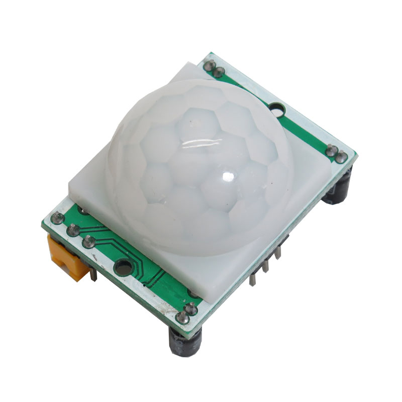
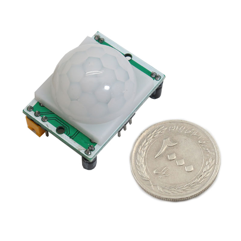
ماژول سنسور تشخیص حرکت مادون قرمز HC-SR501
سنسورهای Passive InfraRed که به اختصار PIR نامیده می شوند ، برای تشخیص حرکت بر مبنای مادون قرمز ناشی از گرمای موجود در محیط کاربرد دارند . از همین رو استفاده از این سنسور ها در سیستم های امنیتی برای تشخیص حرکت انسان و یا ورود های غیر مجاز بسیار رایج می باشد و همچنین سنسورهای تشخیص حرکت از جمله ابزارهای اینترنت اشیا می باشد .
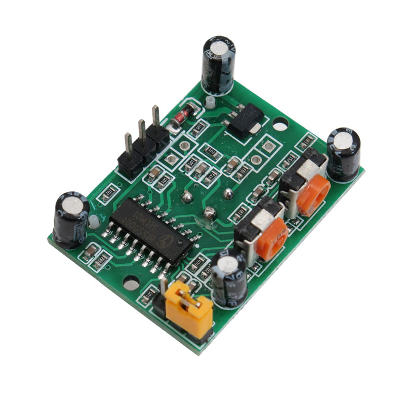
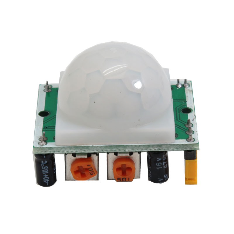
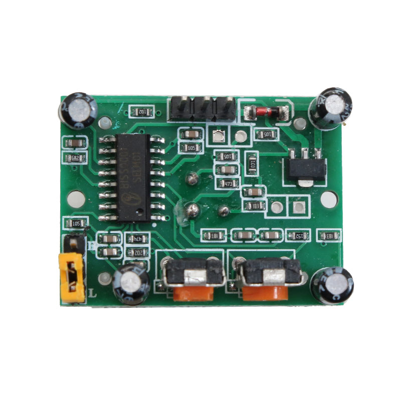
این ماژول دارای سنسور تشخیص حرکت HC-SR501 می باشد و به کمک یک کلاهک نیم دایره ای ، کلیه نورهای دریافتی در محدوده 120 درجه را روی سنسور متمرکز میکند همچنین به وسیله دو پتانسیومتر که برروی آن تعبیه شده ، می توان تنظیمات و کالیبره را انجام داد . از یک پتانسیومتر برای تنظیم فاصله و از پتانسیومتر دیگر جهت فاصله زمانی برای تشخیص حرکت بعد را می توان تنظیم کرد .
خروجی این سنسور می تواند مستقیما به یکی از پایه های میکروکنترلر متصل گردد و در صورت تشخیص هر نوع حرکتی توسط سنسور مقدار این پین یک می گردد . قبل از استفاده از ماژول ، باید عمل کالیبرسیون آن را انجام داد و بعد از اعمال ولتاژ هیچ حرکتی در مقابل ماژول نباید صورت گیرد .
عملکرد جامپر در حالت H به این صورت است که تا زمانی که حرکتی را تشخیص می دهد ، به تولید سیگنال HIGH ادامه خواهد داد . در حالت L خروجی با توجه به مدت زمان تعیین شده توسط پتانسیومترTime ، در حالت HIGH خواهد بود .
کاربرد سنسور HC-SR501 :
- سیستم های امنیتی و ساخت دزدگیر
- کنترل و اتوماسیون صنعتی
- درب های اتوماتیک
- نور پردازی هوشمند
- روشن نمودن چراغ های منازل ، پارگینگ ، ساختمان و ... به وصورت هوشمند و بر اساس تشخیص حرکت
مشخصات سنسور PIR تشخیص حرکت :
- ولتاژ کاری : 20 ~ 5 ولت ( DC )
- مصرف ثابت : 65 میکرو آمپر
- سطح خروجی : 3.3 در حالت high ، صفر ولت در حالت low
- زمان تاخیر : قابل تنظیم ( 18 ~ 0.3 ثانیه )
- تقسیم بندی زمانی : 0.2 ثانیه
- روش های راه اندازی : L شروع به کار مجدد غیر فعال - H شروع به کار مجدد فعال
- محدوده حسایست : در زاویه کمتر از 120 درجه و فاصله کمتر از 7 متر
- دمای کاری : 70 ~ 15- درجه سانتی گراد
- ابعاد PCB برد : 24 * 32 میلی متر ، پیچ 28 میلی متری و دهانه پیچ 2 میلی متری
- ابعاد لنز سنسور ( قطر ) : 23 میلی متر
پایه ها :
پین 1 : پایه منبع تغذیه برای ولتاژ ورودی با مقدار متغیر 5 تا 12 ولت
پین 2 : پایه خروجی برای تغذیه میکروکنترلر
پین 3 : اتصال زمین
مستندات:
جهت دریافت سیم بندی و نمونه کد آردوینو ماژول سنسور تشخیص حرکت مادون قرمز
Descriptions:
Passive InfraRed sensors, which are called PIR for short, are used to detect movement based on infrared light caused by heat in the environment. Therefore, the use of these sensors in security systems to detect human movement or unauthorized entry is very common. Motion detection sensors are among the Internet of Things tools.
The PIR motion detection module, with the help of a semi-circular cap, focuses all the received light in the 120 degree range on the sensor.
This module has a HC-SR501 motion detection sensor and can be adjusted and calibrated using the two potentiometers on it. It can be set from one potentiometer to adjust the distance and from another potentiometer for the time interval to detect the next movement.
The output of this motion detection sensor can be directly connected to one of the microcontroller pins, and if any type of motion is detected by the sensor, the value of this pin is set to one.
Before using the module, it should be calibrated and after applying the voltage, no movement should be made in front of the module.
The function of the jumper in the H mode is that it will continue to generate the HIGH signal until it detects a movement. In L mode, the output will be in HIGH mode according to the time set by the Time potentiometer.
There are two potentiometers on the board to adjust a couple of parameters:
Sensitivity – This sets the maximum distance that motion can be detected. It ranges from 3 meters to approximately 7 meters. The topology of your room can affect the actual range you achieve.
Time – This sets how long that the output will remain HIGH after detection. At the minimum it is 3 seconds, at maximum, it is 300 seconds or 5 minutes.
Finally, the board has a jumper (on some models the jumper is not soldered in). It has two settings:
H – This is the Hold/Repeat/Retriggering In this position, the HC-SR501 will continue to output a HIGH signal as long as it continues to detect movement.
L – This is the Intermittent or No-Repeat/Non-Retriggering In this position the output will stay HIGH for the period set by the TIME potentiometer adjustment.
Application:
Security systems and the construction of burglar alarms
Industrial control and automation
Warning systems
automatic doors
Smart lighting
Turning on the lights of houses, pargings, buildings, etc. intelligently and based on motion detection
Specifications:
Working voltage: 20 ~ 5 volts (DC)
Constant consumption: 65 microamps
Output level: 3.3 in high mode, zero volts in low mode
Delay time: adjustable (18 ~ 0.3 seconds)
Time division: 0.2 seconds
Startup methods: L restart inactive - H restart active
Sensitivity range: at an angle of less than 120 degrees and a distance of less than 7 meters
Working temperature: -15 ~ 70 degrees Celsius
Board PCB dimensions: 24 x 32 mm, 28 mm screw and 2 mm screw hole
Sensor lens dimensions (diameter): 23 mm
Pinout :
Pin 1: Power supply base for input voltage with a variable value of 5 to 12 volts
Pin 2: output pin for feeding the microcontroller
Pin 3: ground connection
Potentiometer Adjustment:
◦ Adjust the distance potentiometer clockwise rotation, increased sensing distance (about 7 meters), on the contrary, the sensing distance
decreases (about 3 meters).
◦ Adjust the delay potentiometer clockwise rotation sensor the delay lengthened (300S), on the contrary, shortens the induction delay (5S).
