موجودی در حال ارسال به انبار
-
30 عدد1404/08/17
هنوز هیچ رایی ثبت نشده است
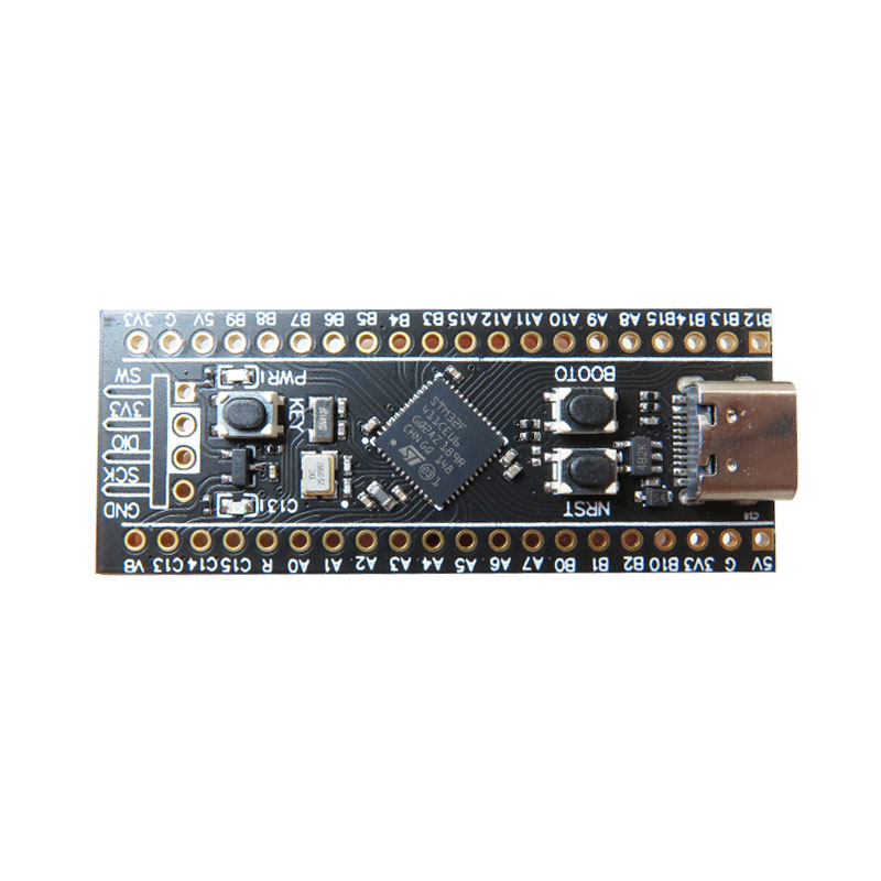
ماژول برد توسعه مدل STM32F411CEU6
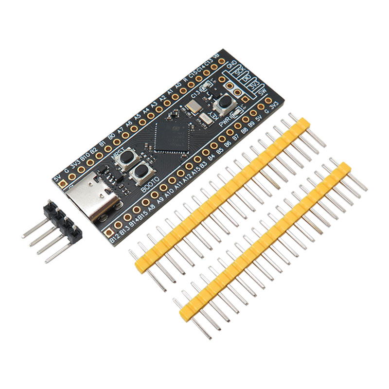
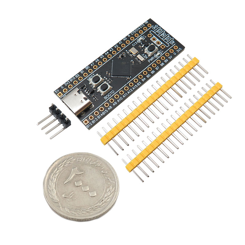
ماژول برد توسعه مدل STM32F411CEU6 برد توسعه یافته سری آرم با قدرت پردازشی بالاتر کورتکس 4 و فرکانس کار 100 مگاهرتز است. ظرفیت حافظه فلش این برد توسعه 512KB و ظرفیت 128KB برای حافظه SRAM دارد و با اضافه کردن حافظه فلش می توان ظرفیت آن را افزایش داد.
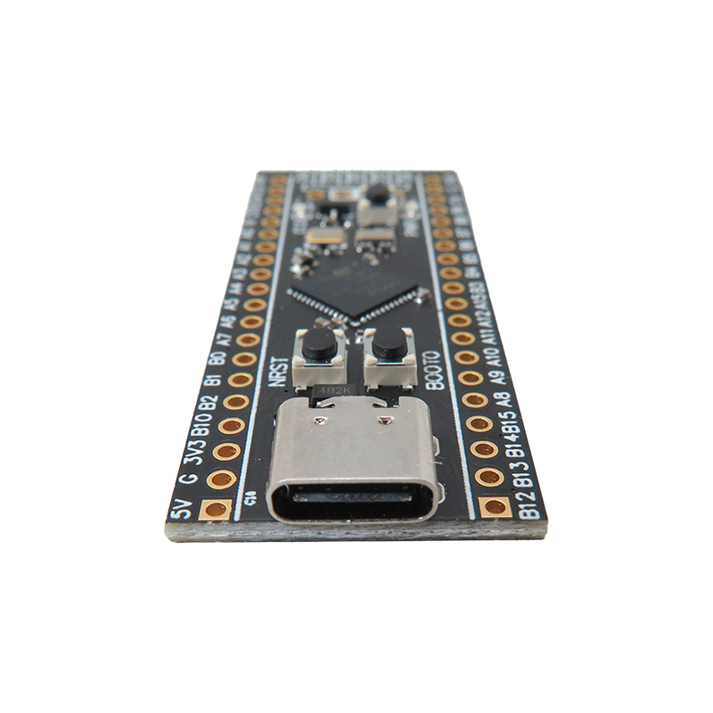
از طریق پورت سی روی برد می توان از طریق آردوینو برد را برنامه ریزی کرد.
خروجی رگولاتور روی برد 3.3 ولت است و برای پروژه های امبدد گزینه مناسبی می باشد.
کاربرد برد توسعه STM32F411CEU6:
- بردهای امبدد
- آموزشی
مشخصات برد توسعه STM32F411CEU6:
- پردازنده برد: STM32F411CEU6
- کورتکس A4
- سازنده: ST-Microelectronics
- حداکثر سرعت کلاک: 100MHz
- پکیج 48 پین UFQFPN
- حافظه فلش: 512KB
- ظرفیت 128 کیلوبایتی SRAM
- آی سی رگولاتور: AP7343
- خروجی رگولاتور: 3.3v 300mA
- دارای پورت سی
- سه دکمه سوییچ Reset, Power, Boot
مستندات:
دیتاشیت چیپ STM32F411
Description:
You can also add an additional flash by soldering an SPI Flash to the board. The board can be programmed using either the onboard Type-C USB connector, the STLink USB dongle, or an external USB to 3.3V TTL adapter.
The STM32F411CEU6 Black Pill is pre-flashed with microPython firmware. You can also program it with Arduino IDE, however doing so will erase the microPython firmware.
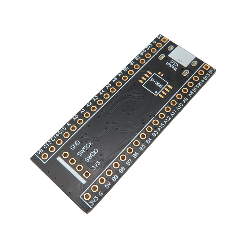
This compact STM32F411 development board can be well embedded in your projects. Featuring the STM32F411CEU6. There is a spot on the bottom for SOIC flash memory, which allows you to solder SPI flash memory to give yourself more space for data logging or file storage.
The board features a Type-C connector and a 3.3V 100mA LDO regulator. Also, a diode is connected in series to prevent power backflow. There are both 25Mhz 9pF high-speed and 32.768Khz 6pF low-speed crystals on board.
This dev board is suitable for advanced users with STM32 development experience, we do not have a detailed tutorial usage for it.
Application:
embedded system
tutorial application
Features:
Part STM32F411CEU6
Manufacturer ST-Microelectronics
Core Arm Cortex-M4
Max. Clock Speed 100MHz
Package UFQFPN 48 pins
FLASH 512KiB
SRAM 128KiB
regulator part: AP7343
Regulator output: 3.3v 300mA
Buttons: Reset, Power, Boot
Pins description:
1. 5V - +5V rail
2. G - Ground plane
3. 3.3 - +3.3V rail
4. B10 - PB10
5. B2 - PB2
6. B1 - PB1
7. B0 - PB0
8. A7 - PA7
9. A6 - PA6
10. A5 - PA5
11. A4 - PA4
12. A3 - PA3
13. A2 - PA2
14. A1 - PA1
15. A0 - PA0
16. R - NRST
17. C15 - PC15
18. C14 - PC14
19. C13 - PC13
20. VB - VBAT
Header 2 pins:
1. B12 - PB12
2. B13 - PB13
3. B14 - PB14
4. B15 - PB15
5. A8 - PA8
6. A9 - PA9
7. A10 - PA10
8. A11 - PA11
9. A12 - PA12
10. A15 - PA15
11. B3 - PB3
12. B4 - PB4
13. B5 - PB5
14. B6 - PB6
15. B7 - PB7
16. B8 - PB8
17. B9 - PB9
18. 5V - +5V rail
19. G - Ground plane
20. 3.3 - +3.3V rail
