2,890,100 تومان
کالا موجود استموجودی انبار : 2 عدد
علاقه مندان : 1 نفر
وضعیت : فعال
تعداد مرجوعی : 0
دنبال کنندگان : 1 نفر
قدمت : 1 سال و 8 ماه و 16 روز
وزن : 235 گرم
کل فروش : عدد
تعداد سفارش ها : 0 سفارش
هنوز هیچ رایی ثبت نشده است
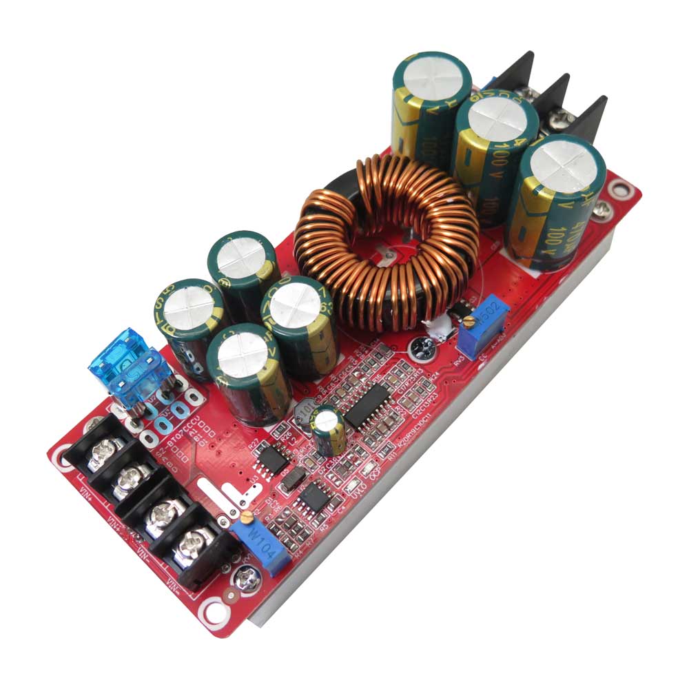
معرفی ماژول افزاینده ولتاژ SZ-BT07CCCV-A و نحوه تنظیم آن
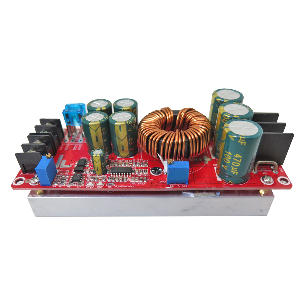
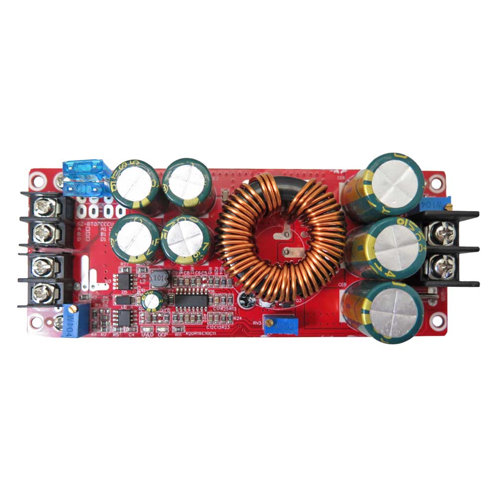
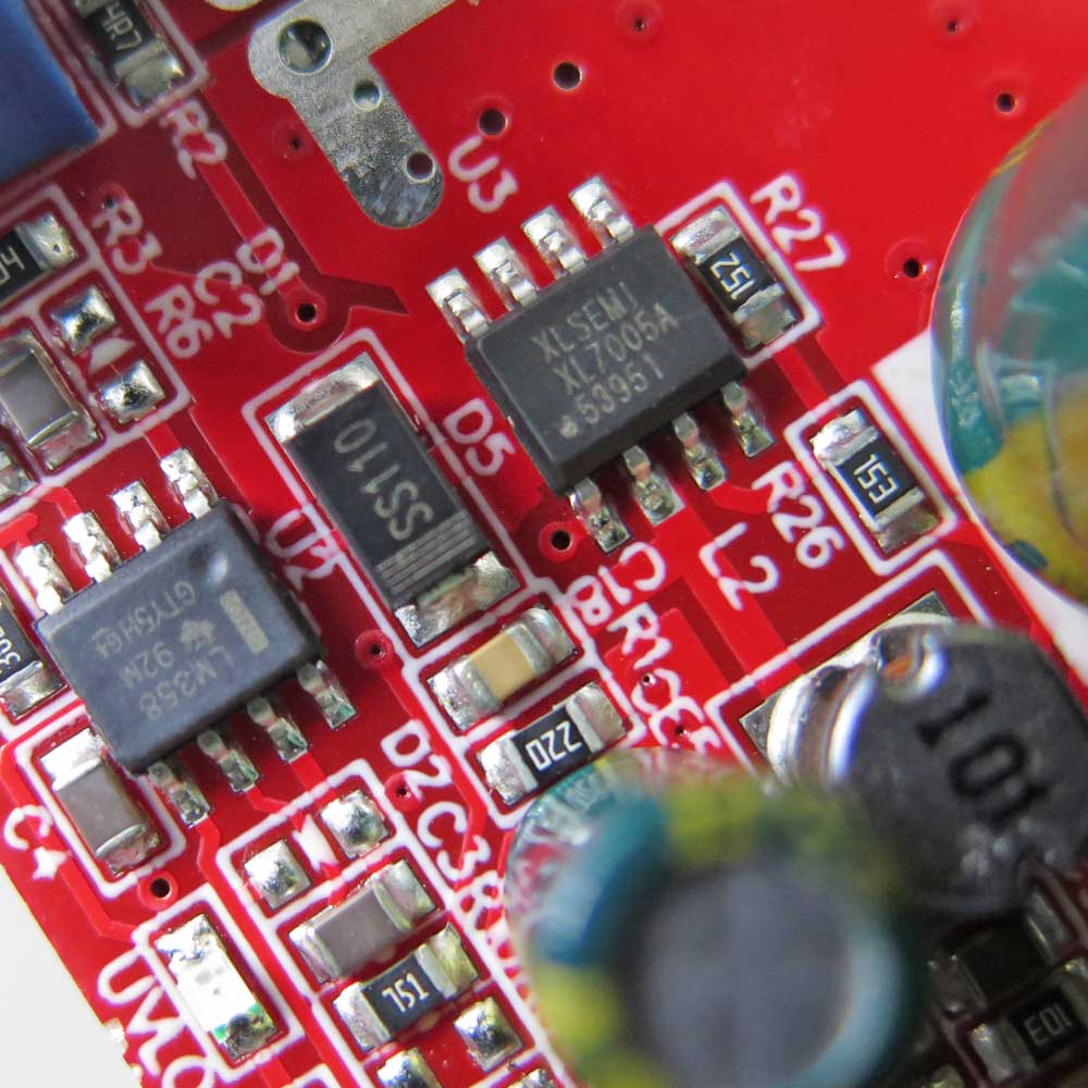
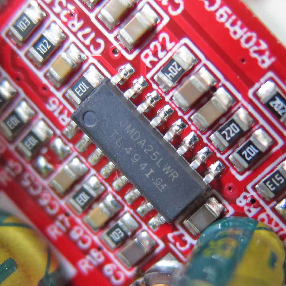
ماژول مبدل DC-DC افزاینده ولتاژ SZ-BT07CCCV برای تبدیل ولتاژ مستقیم به ولتاژ مستقیم بالاتر طراحی شده است. این ماژول با استفاده از مدار کنترل مبتنی بر آی سی TL494 امکان تنظیم ولتاژ خروجی و محدودیت جریان را فراهم می کند و برای راه اندازی مدارها و تجهیزات الکترونیکی سازگار با محدوده ولتاژ و جریان آن قابل استفاده است.
ولتاژ ورودی این ماژول 10 تا 60 ولت DC و محدوده ولتاژ خروجی قابل تنظیم آن 12 تا 83 ولت DC است. حداکثر جریان ورودی 20 آمپر و حداکثر جریان خروجی 18 آمپر اعلام شده است. جریان و توان قابل دستیابی به ولتاژ ورودی، اختلاف ولتاژ ورودی و خروجی، محدودیت های مدار و شرایط خنک کاری بستگی دارد.
توان 1200 وات به عنوان توان نامی محصول اعلام شده است و توان قابل دریافت در عمل به شرایط کاری بستگی دارد. برای مثال، هنگام استفاده از ولتاژ ورودی پایین، تامین توان بالا به جریان ورودی بیشتری نیاز دارد. هنگام کار با بارهای پرمصرف، ظرفیت منبع تغذیه، سیم کشی، اتصالات و خنک کاری را متناسب با جریان مصرفی انتخاب کنید.
کاربرد
- افزایش ولتاژ DC برای تغذیه مدارها و تجهیزات الکترونیکی سازگار با ولتاژ خروجی ماژول.
- ساخت منبع تغذیه DC با ولتاژ خروجی قابل تنظیم در محدوده کاری ماژول.
- استفاده در پروژه های الکترونیکی و آزمایشگاهی که به ولتاژ مستقیم بالاتر از ولتاژ ورودی نیاز دارند.
- استفاده در سامانه های تغذیه باتری، با رعایت ولتاژ مورد نیاز باتری، محدودیت جریان و الزامات شارژ متناسب با نوع باتری.
مشخصات فنی
- مدل: SZ-BT07CCCV
- نوع مبدل: افزاینده ولتاژ DC-DC
- نوع ایزولاسیون: غیر ایزوله
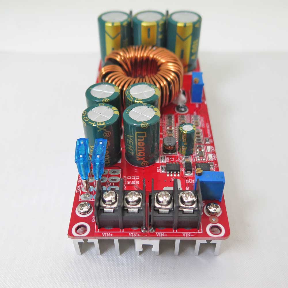
- ولتاژ ورودی: 10 تا 60 ولت DC
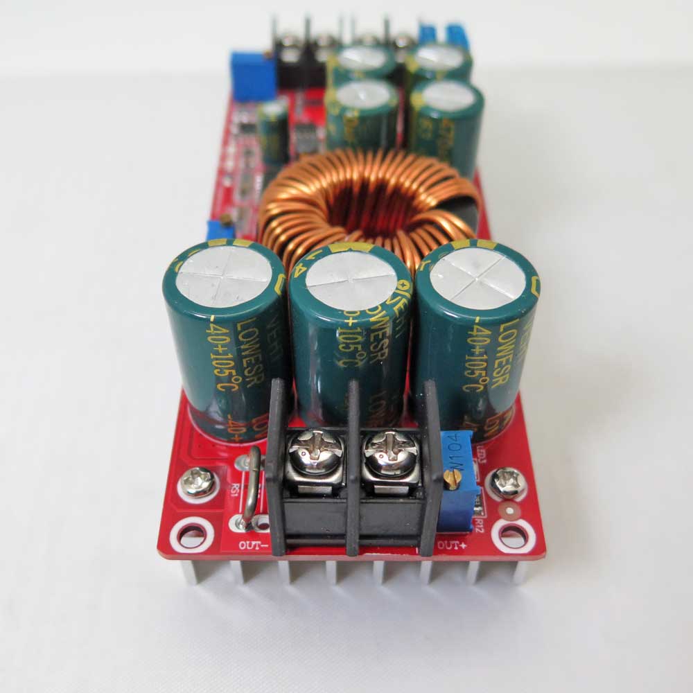
- ولتاژ خروجی قابل تنظیم: 12 تا 83 ولت DC
- حداکثر جریان ورودی اعلام شده: 20 آمپر
- حداکثر جریان خروجی اعلام شده: 18 آمپر
- توان نامی اعلام شده: 1200 وات؛ توان واقعی قابل دریافت به ولتاژ ورودی، جریان و شرایط خنک کاری بستگی دارد.
- آی سی کنترلر PWM: TL494
- فرکانس سوئیچینگ اعلام شده: 150 کیلوهرتز
- تنظیم ولتاژ خروجی: پتانسیومتر CV با علامت V-ADJ
- تنظیم محدودیت جریان: پتانسیومتر CC با علامت A-ADJ
- تنظیم آستانه حفاظت افت ولتاژ ورودی: پتانسیومتر RV1
- نشانگر وضعیت حفاظت افت ولتاژ ورودی: UVLO
- نوع اتصال: ترمینال پیچی
امکانات
- افزایش ولتاژ مستقیم ورودی به ولتاژ مستقیم بالاتر در محدوده کاری ماژول.
- امکان تنظیم ولتاژ خروجی با پتانسیومتر CV یا V-ADJ.
- امکان تنظیم محدودیت جریان خروجی با پتانسیومتر CC یا A-ADJ.
- امکان تنظیم آستانه حفاظت افت ولتاژ ورودی با پتانسیومتر RV1.
- وجود نشانگر UVLO برای نمایش وضعیت حفاظت افت ولتاژ ورودی.
- کنترل مدار مبدل با آی سی PWM مدل TL494.
- طراحی غیر ایزوله برای تبدیل ولتاژ DC به ولتاژ DC بالاتر.
راهنمای تنظیم ولتاژ خروجی
-
برای تنظیم ولتاژ خروجی، ماژول را بدون اتصال بار روشن کنید و مولتی متر مناسب را به خروجی متصل کنید. سپس پتانسیومتر CV یا V-ADJ را به آرامی بچرخانید و مقدار ولتاژ را روی مولتی متر بررسی کنید. هنگام کاهش ولتاژ از مقدار بالا به مقدار پایین، به دلیل ظرفیت خازنی خروجی، ممکن است تغییر مقدار با تاخیر همراه باشد.
راهنمای تنظیم محدودیت جریان
-
برای تنظیم محدودیت جریان، از بار آزمایشی مناسب و ابزار اندازه گیری با رنج صحیح استفاده کنید. آمپرمتر باید به صورت سری با بار قرار بگیرد و هرگز نباید مستقیما به دو سر خروجی متصل شود. پتانسیومتر CC یا A-ADJ برای تنظیم محدودیت جریان خروجی استفاده می شود. پتانسیومتر را به آرامی تنظیم کنید و از وارد کردن فشار بیش از حد به آن خودداری کنید.
-
عملکرد محدودکننده جریان را با بار آزمایشی مناسب بررسی کنید. رفتار مدار هنگام رسیدن به حد جریان به شرایط کاری و طراحی مدار بستگی دارد؛ بنابراین برای کاربردهای حساس، عملکرد ماژول را در محدوده جریان مورد نیاز آزمایش کنید.
راهنمای تنظیم حفاظت افت ولتاژ ورودی UVLO
-
پتانسیومتر RV1 برای تنظیم آستانه حفاظت افت ولتاژ ورودی UVLO استفاده می شود. برای تنظیم، از منبع تغذیه قابل تنظیم و محدودشده از نظر جریان استفاده کنید و ولتاژ ورودی را به آستانه مورد نظر برسانید. سپس RV1 را به آرامی تنظیم کنید تا وضعیت نشانگر UVLO تغییر کند. هنگام تنظیم، ولتاژ ورودی را با مولتی متر کنترل کنید.
-
فعال شدن UVLO لزوما به معنی قطع کامل خروجی از ورودی نیست. این حفاظت برای کنترل عملکرد مبدل هنگام افت ولتاژ ورودی به کار می رود و ممکن است با توقف عملکرد افزایندگی، ولتاژ ورودی همچنان در خروجی دیده شود. اگر قطع کامل باتری یا منبع تغذیه ضروری است، از مدار قطع جداگانه و متناسب با ولتاژ و جریان سیستم استفاده کنید.
نکات مهم هنگام استفاده
- پیش از اتصال بار، ولتاژ خروجی را با مولتی متر بررسی کنید.
- ولتاژ خروجی را از محدوده مجاز دستگاه مصرف کننده بالاتر نبرید.
- از اتصال کوتاه خروجی و معکوس کردن قطب های ورودی و خروجی خودداری کنید.
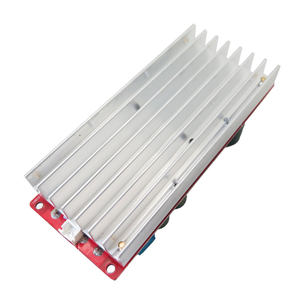
- برای بارهای پرجریان، سیم و اتصالات مناسب انتخاب کنید و خنک کاری کافی فراهم کنید.
- برای تنظیم محدودیت جریان، آمپرمتر را مستقیما به خروجی متصل نکنید.
- در کاربرد باتری، آستانه UVLO را متناسب با نوع باتری و شرایط کاری انتخاب کنید. این حفاظت را جایگزین سامانه کامل مدیریت باتری در نظر نگیرید.
- این ماژول غیر ایزوله است؛ مدار ورودی و خروجی را با فرض جداسازی الکتریکی ایمن طراحی نکنید.
سوالات متداول درباره ماژول SZ-BT07CCCV
-
ولتاژ ورودی و خروجی ماژول چقدر است؟
ولتاژ ورودی ماژول 10 تا 60 ولت DC و ولتاژ خروجی قابل تنظیم آن 12 تا 83 ولت DC است. -
پتانسیومترهای CV، CC و RV1 چه کاربردی دارند؟
پتانسیومتر CV یا V-ADJ برای تنظیم ولتاژ خروجی، پتانسیومتر CC یا A-ADJ برای تنظیم محدودیت جریان و پتانسیومتر RV1 برای تنظیم آستانه حفاظت افت ولتاژ ورودی UVLO استفاده می شود. آی سی TL494 نیز وظیفه کنترل PWM مدار را بر عهده دارد. -
آیا UVLO خروجی را کاملا قطع می کند؟
فعال شدن UVLO لزوما به معنی قطع کامل خروجی از ورودی نیست. هنگام افت ولتاژ ورودی، عملکرد افزایندگی ممکن است متوقف شود، اما ولتاژ ورودی همچنان در خروجی دیده شود. برای قطع کامل منبع تغذیه باید از مدار قطع مناسب استفاده شود. -
آیا می توان جریان را با اتصال مستقیم آمپرمتر تنظیم کرد؟
خیر. آمپرمتر را مستقیما به دو سر خروجی وصل نکنید. برای اندازه گیری جریان باید ابزار مناسب را به صورت سری با بار آزمایشی متصل کنید. -
آیا ماژول همیشه توان 1200 وات را تامین می کند؟
خیر. توان 1200 وات مقدار نامی اعلام شده برای محصول است. توان قابل دریافت به ولتاژ و جریان ورودی، ولتاژ خروجی، محدودیت های مدار و شرایط خنک کاری بستگی دارد.
مستندات:
راهنمای تنظیم ماژول افزاینده ولتاژ SZ-BT07CCCV-A
SZ-BT07CCCV DC-DC Boost Converter Module
The SZ-BT07CCCV is a non-isolated DC-DC boost converter module designed to convert a direct-current input into a higher direct-current output voltage. It uses a TL494 PWM controller and provides adjustable output voltage and current limiting for compatible electronic circuits and equipment.
The input voltage range is 10 to 60V DC, and the adjustable output voltage range is 12 to 83V DC. The stated maximum input current is 20A, and the stated maximum output current is 18A. Actual available current and power depend on the input voltage, the difference between input and output voltages, circuit limitations, and cooling conditions.
The 1200W designation is the nominal power rating stated for the product. Actual output power depends on operating conditions. At a lower input voltage, delivering high output power requires a higher input current. Select the power supply, wiring, connectors, and cooling system according to the required load.
Applications
- Increasing DC voltage to power electronic circuits and equipment compatible with the output range.
- Building an adjustable DC power supply within the module's operating limits.
- Electronic and laboratory projects requiring a DC voltage higher than the input supply.
- Selected battery power systems, provided that battery voltage, current limits, and charging requirements are properly addressed.
Technical Specifications
- Model: SZ-BT07CCCV
- Converter type: DC-DC boost converter
- Isolation: Non-isolated
- Input voltage: 10 to 60V DC
- Adjustable output voltage: 12 to 83V DC
- Stated maximum input current: 20A
- Stated maximum output current: 18A
- Nominal power rating: 1200W; actual output power depends on input voltage, current, and cooling conditions.
- PWM controller IC: TL494
- Stated switching frequency: 150kHz
- Output voltage adjustment: CV potentiometer marked V-ADJ
- Current limit adjustment: CC potentiometer marked A-ADJ
- Input undervoltage threshold adjustment: RV1 potentiometer
- Input undervoltage protection indicator: UVLO
- Connection type: Screw terminals
Features
- Boosts a DC input voltage to a higher DC output voltage within the module's operating range.
- Adjustable output voltage using the CV or V-ADJ potentiometer.
- Adjustable output current limit using the CC or A-ADJ potentiometer.
- Adjustable input undervoltage threshold using the RV1 potentiometer.
- UVLO indicator for input undervoltage protection status.
- PWM control using the TL494 controller IC.
- Non-isolated DC-DC boost conversion design.
Output Voltage Adjustment
-
To adjust the output voltage, power the module without a connected load and connect a suitable multimeter across the output terminals. Turn the CV or V-ADJ potentiometer slowly while monitoring the meter. Because of the output capacitors, the voltage may respond slowly when being adjusted from a higher setting to a lower one.
Current Limit Adjustment
-
Use a suitable test load and correctly rated measuring equipment when setting the current limit. Connect an ammeter in series with the load. Never connect an ammeter directly across the output terminals. The CC or A-ADJ potentiometer is used to adjust the output current limit. Turn the potentiometer slowly and do not force it past its mechanical stop.
-
Test the current limiting behavior with a suitable load. The circuit response at the current limit depends on operating conditions and circuit design. For sensitive applications, test the module within the required current range before use.
Input Undervoltage Protection Adjustment (UVLO)
-
The RV1 potentiometer adjusts the input undervoltage protection threshold. Use an adjustable DC power supply with an appropriate current limit and bring the input voltage to the desired threshold. Slowly adjust RV1 until the UVLO indicator changes state. Monitor the input voltage with a multimeter during adjustment.
-
UVLO does not necessarily disconnect the output completely from the input. When the input voltage falls below the set threshold, boost operation may stop while the input voltage remains present at the output. If complete battery or power supply disconnection is required, use a separate disconnect circuit rated for the system voltage and current.
Important Operating Notes
- Check the output voltage with a multimeter before connecting a load.
- Do not set the output voltage above the permitted rating of the connected equipment.
- Avoid shorting the output or reversing the input or output polarity.
- Use suitable wires and connectors for high-current operation and provide adequate cooling.
- Never connect an ammeter directly across the output when adjusting the current limit.
- For battery applications, select the UVLO threshold according to the battery type and operating requirements. Do not treat this feature as a complete battery management system.
- The module is non-isolated. Do not design the input and output circuits on the assumption that they are electrically isolated.
Package Contents
The package contents are not specified in this description, so unconfirmed accessories or additional items are not listed as included.
Frequently Asked Questions About the SZ-BT07CCCV
-
What are the input and output voltage ranges?
The input voltage range is 10 to 60V DC, and the adjustable output voltage range is 12 to 83V DC. -
What do the CV, CC, and RV1 potentiometers do?
The CV or V-ADJ potentiometer adjusts the output voltage, the CC or A-ADJ potentiometer adjusts the output current limit, and the RV1 potentiometer adjusts the input undervoltage protection threshold. The TL494 IC controls the PWM circuit. -
Does UVLO completely disconnect the output?
Not necessarily. When the input voltage falls below the set threshold, boost operation may stop while the input voltage remains present at the output. Use a suitable disconnect circuit if complete disconnection is required. -
Can an ammeter be connected directly to the output to set the current?
No. Never connect an ammeter directly across the output. Use a suitable test load and connect the ammeter in series with that load. -
Can the module always deliver 1200W?
No. The 1200W value is the nominal power rating stated for the product. Actual output power depends on input voltage, input current, output voltage, circuit limitations, and cooling conditions.