122,760 تومان
کالا موجود استموجودی انبار : 90 عدد
علاقه مندان : 18 نفر
وضعیت : فعال
تعداد مرجوعی : 1
دنبال کنندگان : 20 نفر
قدمت : 11 سال و 3 ماه و 21 روز
وزن : 10 گرم
کل فروش : 1896 عدد
تعداد سفارش ها : 826 سفارش
3 از 5.0 با 6 رای
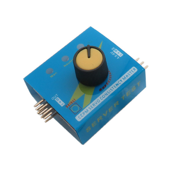
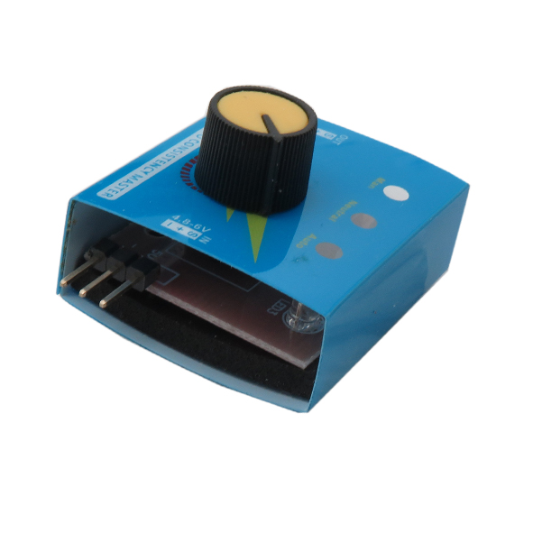
تستر سروو موتور 3 کاناله - Servo Tester
سروو موتورها نوعی از موتورهای الکتریکی هستند که با هدف بکارگیری در سیستمهای کنترل فیدبک طراحی میشود. اینرسی در این موتورها پایین بوده و در نتیجه تغییر سرعت در این موتورها بسیار سریع می باشد. این موتورها قابلیت کارکرد در زاویه مشخص، سرعت و قدرت بالا را دارند. موتورهای سروو نیاز به مدارهای خاصی جهت راه اندازی دارند که در همه مواقع میکروکنترلر در دسترس نخواهد بود.
برای استفاده از این تستر باید ولتاژ ورودی بین 4.8 - 6 ولت را به قسمت IN متصل کرد و طرف دیگر OUT که دارای 3 خروجی است، را به سروو وصل کرد.
این تستر امکان کنترل حداکثر سه موتور را به کاربر می دهد که با چرخش ولوم قرار گرفته بر روی دستگاه می توانید حرکت موتور را کنترل کنید.
استفاده راحت جهت آزمایش و تنظیم سروو موتورها، پایداری خوب و دقت بالا از ویژگی های این تستر می باشد
کاربرد تستر سرو موتور 3 کاناله :
- آزمایش و کالیبره کردن موتورهای سرو
مشخصات تستر سرو موتور 3 کاناله :
- ولتاژ ورودی: 6 ~ 4.2 ولت DC
- خروجی: کمتر مساوی 15 میلی آمپر
- مدت زمان سیگنال خروجی: 1.5 میلی ثانیه با تلرانس 0.5
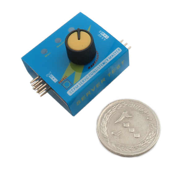
- ابعاد: 17 × 32 × 46 میلی متر
Description:
The servo tester is useful to center a servo, manually move the servo arm and automatically cycle the servo the full amount of travel. It is useful for building RC airplanes without having to hook up the receiver and transmitter to center servos.
The servo motor can be moved to a desired angular position by sending PWM (pulse width modulated) signals on the signal (control) wire. Usually, a pulse of width varying from 1 millisecond to 2 milliseconds in a repeated time frame is sent to the servo for around 50 times in a second. The width of the pulse determines the angular position.
The LM555 is a highly stable device for generating accurate time delays or oscillation. Additional terminals are provided for triggering or resetting if desired. In the time delay mode of operation, the time is precisely controlled by one external resistor and capacitor.
For a stable operation as an oscillator, the free-running frequency and duty cycle are accurately controlled with two external resistors and one capacitor. The circuit may be triggered and reset on falling waveforms, and the output circuit can source or sink up to 200 mA or drive TTL circuits.
Instructions:
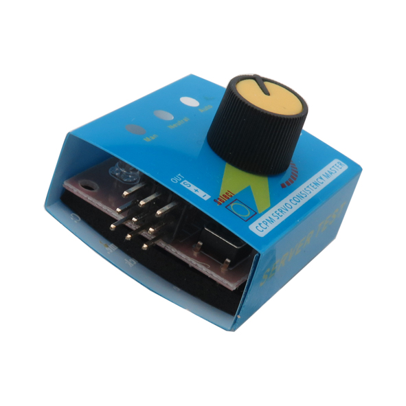
The left side of the tester connects to the servo. The pins divided into three groups of upper, middle, and lower, which can be connected to three servos.
The single row of pins on the right is connected to the power supply. Be careful not to connect it inversely. If the power supply is reversed, the IC will burn.
The pin corresponding to the S identifier does not need to be ignored. After turning on the power, the blue light will be on at the same time, and then only the first one on the left will be tested for manual adjustment of the potentiometer.
Press the button, the middle light turns on, it will be the centering test; the third light turns on, it will automatically test.
The connection method of the test ESC is the same as that of the servo, but the input terminal should not be connected to the power supply. The test motor needs to be connected to the ESC first, just like the ESC test!
Application:
Testing and calibrating servo motors
Features:
Input: DC 4.2-6.0V
Output: ≤ 15mA
Output Signal: 1.5ms ± 0.5ms
Size: 46mm x 32mm x 17mm
Operation Modes :
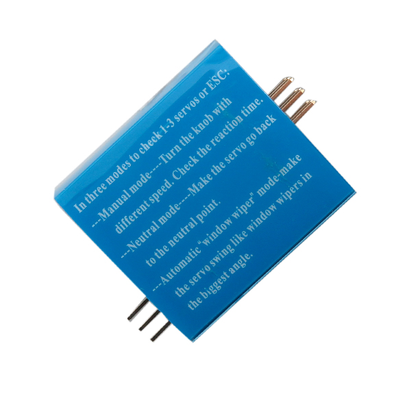
Automatic Mode: The Automatic ’’Window Wiper’’ mode makes the servo swing like a window wiper in the largest angle possible.
Manual Mode: The Manual Mode allows you to turn the knob to different speeds and check the reaction time.
Neutral: The Neutral mode makes the servo go back to the neutral point.
Note: This tester can not test the servo more than 55 grams.
